Integration einer Dimplex-Wärmepumpe in Home Assistant mit MQTT

Einleitung

Die Integration smarter Heizsysteme in eine Home-Automation-Lösung wie Home Assistant (HASS) ermöglicht nicht nur die zentrale Steuerung, sondern auch detaillierte Analysen und Automatisierungen. Dieser Beitrag zeigt, wie eine Dimplex-Wärmepumpe mit der NWPM Touch-Erweiterung über MQTT mit Home Assistant verbunden wird. Wir richten uns an fortgeschrittene Nutzer, die mit MQTT und YAML bereits vertraut sind.


Die Anleitung basiert auf den von Dimplex zur verfügung gestellten Informationen:
https://dimplex.atlassian.net/wiki/spaces/DW/pages/3021930597/MQTT+Anbindung

Voraussetzungen

Für die Integration benötigen Sie:

  1. Einen Home Assistant Server, idealerweise auf einem Raspberry Pi, Proxmox oder vergleichbarer Hardware.
  2. Eine Dimplex-Wärmepumpe mit Touch-Display und einer NWPM Touch-Erweiterung.
  3. Einen MQTT-Broker, z. B. Mosquitto, entweder als Standalone-Server oder auf der NWPM-Baugruppe.

Optional: Ein Broker-to-Broker-Setup, um einen externen Broker mit dem integrierten MQTT-Server der NWPM zu verbinden.


Besonderheiten bei meiner Dimplex-MQTT-Anbindung

Die Dimplex NWPM Touch-Erweiterung bietet einen eingebauten MQTT-Server, der entweder direkt genutzt oder wie bei mir über ein Broker-to-Broker-Setup mit einem externen Broker verbunden werden kann. Die Konfigurationsdatei für das Broker-to-Broker-Setup sieht beispielsweise so aus:

# connection dimplex
connection dimplex
address 192.168.x.x:61894
remote_username mqtt
remote_password <password>
try_private true
bridge_insecure true

topic # out 0
topic # in 0

In unserem Setup nutzen wir einen Mosquitto-Broker auf Proxmox in einem LXC-Container und empfehlen, diesen für mehr Flexibilität zu verwenden.

Derzeit nutze ich nur die Informationen aus der Wärmepumpe, die Steuerung werde ich zu einem späteren Zeitpunkt einrichten.


Schritt 1: MQTT in Home Assistant aktivieren

Stellen Sie sicher, dass der MQTT-Integration in Home Assistant aktiviert ist. Dies erfolgt über die configuration.yaml oder über die Benutzeroberfläche von Home Assistant.

Beispiel für die configuration.yaml:

mqtt:
  broker: 192.168.x.x  # IP-Adresse des MQTT-Brokers
  username: mqtt
  password: <password>

Starten Sie Home Assistant neu, um die Änderungen zu übernehmen.


Schritt 2: YAML-Konfiguration der Sensoren

Um die Daten der Wärmepumpe in Home Assistant anzuzeigen, fügen Sie die Sensoren in der configuration.yaml hinzu. Hier ist eine Übersicht wichtiger Sensoren:

  sensor:
    - name: "Wärmepumpe Außentemperatur (R1)"
      unique_id: '1301a_temperature'
      state_topic: "extern/broadcast/twin_reported_state"
      value_template: "{{ value_json.telemetry['1301a'] }}"
      unit_of_measurement: "°C"
      device_class: temperature
      qos: 1
    - name: "Wärmepumpe Temperatur Ruecklauf (R2)"
      unique_id: '1294a_temperature'
      state_topic: "gateway/broadcast/changed_on/modbus"
      value_template: "{{ value_json['1294a']['value_batch']['1294a']['value'] }}"
      unit_of_measurement: "°C"
      device_class: temperature
      qos: 1
    - name: "Wärmepumpe Temperatur Vorlauf (R9)"
      unique_id: '1300a_temperature'
      state_topic: "gateway/broadcast/changed_on/modbus"
      value_template: "{{ value_json['1300-1301a']['value_batch']['1300a']['value'] }}"
      unit_of_measurement: "°C"
      device_class: temperature
      qos: 1
    - name: "Wärmepumpe Temperatur Warmwassersoll"
      unique_id: '1042i_temperature'
      state_topic: "extern/broadcast/twin_reported_state"
      value_template: "{{ value_json.telemetry['1042i'] }}"
      unit_of_measurement: "°C"
      device_class: temperature
      qos: 1
    - name: "Wärmepumpe Temperatur Warmwassersoll Max"
      unique_id: '1044i_temperature'
      state_topic: "extern/broadcast/twin_reported_state"
      value_template: "{{ value_json.telemetry['1044i'] }}"
      unit_of_measurement: "°C"
      device_class: temperature
      qos: 1
    - name: "Wärmepumpe Temperatur Warmwassersoll Min"
      unique_id: '1045i_temperature'
      state_topic: "extern/broadcast/twin_reported_state"
      value_template: "{{ value_json.telemetry['1045i'] }}"
      unit_of_measurement: "°C"
      device_class: temperature
      qos: 1
    - name: "Wärmepumpe Temperatur Warmwasser (R3)"
      unique_id: '1305a_temperature'
      state_topic: "gateway/broadcast/changed_on/modbus"
      value_template: "{{ value_json['1305a']['value_batch']['1305a']['value'] }}"
      unit_of_measurement: "°C"
      device_class: temperature
      qos: 1      
    - name: "Wärmepumpe Status (Telemetry)"
      unique_id: '530u_status_telemetry'
      state_topic: "extern/broadcast/twin_reported_state"
      value_template: "{{ value_json.telemetry['530i'] }}"
      qos: 1         

    - name: "Wärmepumpe Sperrmeldungen (Telemetry)"
      unique_id: '533i_sperrmeldungen_telemetry'
      state_topic: "extern/broadcast/twin_reported_state"
      value_template: "{{ value_json.telemetry['533i'] }}"
      qos: 1        

    - name: "Wärmepumpe Störmeldungen (Telemetry)"
      unique_id: '531i_stoermeldungen_telemetry'
      state_topic: "extern/broadcast/twin_reported_state"
      value_template: "{{ value_json.telemetry['531i'] }}"
      qos: 1        

    - name: "Wärmepumpe Sensorfehler (Telemetry)"
      unique_id: '532i_sensorfehler_telemetry'
      state_topic: "extern/broadcast/twin_reported_state"
      value_template: "{{ value_json.telemetry['532i'] }}"
      qos: 1        
      
    - name: "Wärmepumpe Status"
      unique_id: '530i_status'
      state_topic: "gateway/broadcast/changed_on/modbus"
      value_template: "{{ value_json['530-533i']['value_batch']['530i']['value'] }}"
      qos: 1   
 
    - name: "Wärmepumpe Verdichter 1"
      unique_id: '1500d_status_telemetry'
      state_topic: "gateway/broadcast/changed_on/modbus"
      value_template: "{{ value_json['1500d']['value_batch']['1500d']['value'] }}"
      qos: 1

    - name: "Wärmepumpe Verdichter 2"
      unique_id: '1501i_status_telemetry'
      state_topic: "extern/broadcast/twin_reported_state"
      value_template: "{{ value_json.telemetry['1501i'] }}"
      qos: 1

    - name: "Wärmepumpe Ventilator (M2)"
      unique_id: '1502d_status_telemetry'
      state_topic: "gateway/broadcast/changed_on/modbus"
      value_template: "{{ value_json['1502-1505d']['value_batch']['1502d']['value'] }}"
      qos: 1

    - name: "Wärmepumpe Primärpumpe (M11)"
      unique_id: '1506d_status_telemetry'
      state_topic: "gateway/broadcast/changed_on/modbus"
      value_template: "{{ value_json['1505-1507d']['value_batch']['1506d']['value'] }}"
      qos: 1

    - name: "Wärmepumpe Heizungspumpe (M13)"
      unique_id: '1512d_status_telemetry'
      state_topic: "extern/broadcast/twin_reported_state"
      value_template: "{{ value_json.telemetry['1512d'] }}"
      qos: 1

    - name: "Wärmepumpe Warmwasserpumpe (M18)"
      unique_id: '1517d_status_telemetry'
      state_topic: "gateway/broadcast/changed_on/modbus"
      value_template: "{{ value_json['1516-1517d']['value_batch']['1517d']['value'] }}"
      qos: 1

    - name: "Wärmepumpe Zusatzumwälzpumpe (M16)"
      unique_id: '1516d_status_telemetry'
      state_topic: "gateway/broadcast/changed_on/modbus"
      value_template: "{{ value_json['1516-1517d']['value_batch']['1516d']['value'] }}"
      qos: 1

    - name: "Wärmepumpe Heizungspumpe (M15)"
      unique_id: '1514d_status_telemetry'
      state_topic: "extern/broadcast/twin_reported_state"
      value_template: "{{ value_json.telemetry['1514d'] }}"
      qos: 1

    - name: "Wärmepumpe Sammelstörmeldung (H5)"
      unique_id: '1523d_status_telemetry'
      state_topic: "extern/broadcast/twin_reported_state"
      value_template: "{{ value_json.telemetry['1523d'] }}"
      qos: 1

    - name: "Wärmepumpe Heizungspumpe (M20)"
      unique_id: '1515d_status_telemetry'
      state_topic: "extern/broadcast/twin_reported_state"
      value_template: "{{ value_json.telemetry['1515d'] }}"
      qos: 1

Weitere Sensoren, wie für Warmwassersolltemperaturen, Sperrmeldungen oder Pumpenstatus, können auf ähnliche Weise hinzugefügt werden. Ich habe noch nicht alle Werte zu 100% geprüft und je nach ausstattung der Wärmepumpe z.B. mit 2. Heizkreislauf, Solar oder Schwimbad anbindung gibt es auch noch mehr Werte die Interessant sein können. Dazu kann man die Adressen auf der Wiki Seite von Dimplex nachschlagen.

Hier ist eine detaillierte Erklärung der einzelnen Elemente anhand des Beispielsensors „Wärmepumpe Außentemperatur (R1)“:


YAML-Abschnitt:

sensor:
  - name: "Wärmepumpe Außentemperatur (R1)"
    unique_id: '1301a_temperature'
    state_topic: "extern/broadcast/twin_reported_state"
    value_template: "{{ value_json.telemetry['1301a'] }}"
    unit_of_measurement: "°C"
    device_class: temperature
    qos: 1

1. sensor

Die oberste Ebene definiert einen oder mehrere Sensoren. In diesem Fall wird eine Liste von Sensoren definiert, daher wird ein - verwendet, um den einzelnen Sensor zu beschreiben.


2. name

name: "Wärmepumpe Außentemperatur (R1)"
  • Beschreibung: Der Anzeigename des Sensors, der in der Benutzeroberfläche von Home Assistant erscheint.
  • Empfehlung: Wählen Sie einen klaren und eindeutigen Namen, um den Sensor einfach zu identifizieren.

3. unique_id

unique_id: '1301a_temperature'
  • Beschreibung: Eine eindeutige ID für den Sensor. Sie ermöglicht es Home Assistant, den Sensor auch nach Änderungen in der Konfiguration wiederzuerkennen.
  • Hinweis: Verwenden Sie eine konsistente Struktur, idealerweise basierend auf der Datenquelle. Hier wurde der Modbus-Registercode 1301a verwendet, ergänzt durch _temperature zur besseren Lesbarkeit.

4. state_topic

state_topic: "extern/broadcast/twin_reported_state"
  • Beschreibung: Das MQTT-Topic, aus dem der Sensor seine Daten bezieht.
  • Beispiel: In diesem Fall hört der Sensor auf Nachrichten im Topic extern/broadcast/twin_reported_state.
  • Wichtig: Die Topics müssen exakt mit denen übereinstimmen, die die NWPM-Baugruppe sendet.

5. value_template

value_template: "{{ value_json.telemetry['1301a'] }}"
  • Beschreibung: Ein Template, um die empfangenen Daten aus dem MQTT-Payload zu extrahieren.
  • Details:
    • value_json: Nimmt an, dass die empfangene Nachricht ein JSON-Format hat.
    • telemetry['1301a']: Greift auf das Feld 1301a innerhalb der telemetry-Struktur zu. Dieses Feld enthält den Wert für die Außentemperatur.
  • Empfehlung: Überprüfen Sie die MQTT-Nachrichtenstruktur mit Tools wie MQTT Explorer, um sicherzustellen, dass der Zugriff korrekt definiert ist.

6. unit_of_measurement

unit_of_measurement: "°C"
  • Beschreibung: Gibt die Einheit an, in der der Wert dargestellt wird.
  • Beispiel: In diesem Fall wird die Temperatur in Grad Celsius (°C) angezeigt.
  • Wichtig: Home Assistant verwendet diese Einheit auch für Konvertierungen und Darstellungen in Diagrammen.

7. device_class

device_class: temperature
  • Beschreibung: Definiert die Art des Sensors (z. B. Temperatur, Feuchtigkeit, Batterie).
  • Beispiel: Der Wert temperature signalisiert Home Assistant, dass der Sensor Temperaturdaten liefert. Dies beeinflusst, wie die Daten dargestellt werden (z. B. mit einem Thermometer-Symbol).

8. qos

qos: 1
  • Beschreibung: Die Quality of Service (QoS)-Stufe für MQTT-Nachrichten.
    • 0 (Default): Keine Zustellungsgarantie.
    • 1: Mindestens einmalige Zustellung (empfohlen für wichtige Daten).
    • 2: Genau einmalige Zustellung (weniger häufig verwendet).
  • Empfehlung: Für Sensoren, bei denen Datenintegrität wichtig ist, sollte mindestens QoS 1 verwendet werden.

Zusätzliche Hinweise zur Konfiguration

  • Validierung: Nach der Einrichtung der YAML-Datei kann die Konfiguration in Home Assistant über Einstellungen → Einstellungen prüfen validiert werden.
  • Fehlerbehebung: Falls der Sensor nicht funktioniert, überprüfen Sie:
    1. Ob MQTT-Nachrichten im definierten Topic empfangen werden (z. B. mit MQTT Explorer).
    2. Ob das value_template korrekt auf die JSON-Daten zugreift.
    3. Ob die Verbindung zum Broker korrekt eingerichtet ist.

Mit dieser detaillierten Erklärung können Sie ähnliche Sensoren für andere Werte der Wärmepumpe einrichten.


Schritt 3: Zusätzliche Status-Mappings

Um die rohen Statuswerte der Wärmepumpe besser lesbar zu machen, können Sie benutzerdefinierte Templates in YAML definieren. Ein Beispiel für das Mapping des Betriebsstatus:

  - sensor:
      - name: "Dimplex Status"
        unique_id: "dimplex_status_mapped"
        state: >
          {% set mapping = {
            0: "Aus",
            1: "Aus",
            2: "Heizen",
            3: "Schwimmbad",
            4: "Warmwasser",
            5: "Kühlen",
            10: "Abtauen",
            11: "Durchflussüberwachung",
            24: "Verzögerung Betriebsmodusumschaltung"
          } %}
          {{ mapping.get(states('sensor.warmepumpe_status_telemetry') | int, "Unbekannt") }}
  - sensor:
      - name: "Dimplex Sperrmeldungen"
        unique_id: "dimplex_Sperrmeldungen_mapped"
        state: >
          {% set mapping = {
            0: "keine Sperre",
            2: "Volumenstrom",
            5: "Funktionskontrolle",
            6: "Einsatzgrenze HT",
            7: "Systemkontrolle",
            8: "Verzögerung Umschaltung Kühlen",
            9: "Pumpenvorlauf",
            10: "Mindeststandzeit",
            11: "Netzbelastung",
            12: "Schaltspielsperre",
            13: "Warmwasser Nacherwärmung",
            14: "Regenerativ",
            15: "EVU-Sperre",
            16: "Sanftanlasser",
            17: "Durchfluss",
            18: "Einsatzgrenze Wärmepumpe",
            19: "Hochdruck",
            20: "Niederdruck",
            21: "Einsatzgrenze Wärmequelle",
            23: "System Grenze",
            24: "Last Primärkreis",
            25: "Sperre Extern",
            31: "Aufwärmen",
            33: "EvD Initialisierung",
            34: "2. Wärmeerzeuger freigegeben",
            35: "Störung (siehe Kapitel Störmeldungen)"
          } %}
          {{ mapping.get(states('sensor.warmepumpe_sperrmeldungen_telemetry') | int, "Unbekannt") }}
  - sensor:
      - name: "Dimplex Störmeldung"
        unique_id: "dimplex_stoermeldung_mapped"
        state: >
          {% set mapping = {
            0: "kein Fehler",
            1: "Fehler N17.1",
            2: "Fehler N17.2",
            3: "Fehler N17.3",
            4: "Fehler N17.4",
            6: "Elektronisches Ex.Ventil",
            10: "WPIO",
            12: "Inverter",
            13: "WQIF",
            15: "Sensorik (siehe Kapitel Sensorfehler)",
            16: "Niederdruck Sole",
            19: "!Primärkreis",
            20: "!Abtauen",
            21: "!Niederdruck Sole",
            22: "!Warmwasser",
            23: "!Last Verdichter",
            24: "!Codierung",
            25: "!Niederdruck",
            26: "!Frostschutz",
            28: "!Hochdruck",
            29: "!Temperatur Differenz",
            30: "!Heißgasthermostat",
            31: "!Durchfluss"
          } %}
          {{ mapping.get(states('sensor.warmepumpe_stormeldungen_telemetry') | int, "Unbekannt") }}
  - sensor:
      - name: "Dimplex Sensorfehler"
        unique_id: "dimplex_sensorfehler_mapped"
        state: >
          {% set mapping = {
            0: "kein Fehler",
            1: "Außenfühler (R1)",
            2: "Rücklauffühler (R2)",
            3: "Warmwasserfühler (R3)",
            4: "Codierung (R7)",
            5: "Vorlauffühler (R9)",
            6: "2. Heizkreisfühler (R5)",
            7: "3. Heizkreisfühler (R13)",
            8: "Regenerativfühler (R13)",
            9: "Raumfühler 1",
            10: "Raumfühler 2",
            11: "Fühler Wärmequellenaustritt (R6)",
            12: "Fühler Wärmequelleneintritt (R24)*",
            14: "Kollektorfühler (R23)",
            15: "Niederdrucksensor (R25)",
            16: "Hochdrucksensor (R26)",
            17: "Raumfeuchte 1",
            18: "Raumfeuchte 2",
            19: "Fühler Frostschutz-Kälte",
            20: "Heißgas",
            21: "Rücklauffühler (R2.1)",
            22: "Schwimmbadfühler (R20)",
            23: "Vorlauffühler Kühlen Passiv (R11)",
            24: "Rücklauffühler Kühlen Passiv (R4)",
            26: "Fühler Solarspeicher (R22)",
            28: "Anforderungsfühler Heizen (R2.2)",
            29: "RTM Econ",
            30: "Anforderungsfühler Kühlen (R39)"
          } %}
          {{ mapping.get(states('sensor.warmepumpe_sensorfehler_telemetry') | int, "Unbekannt") }}

Dieses Mapping wird im Frontend von Home Assistant als Klartext angezeigt und verbessert die Benutzerfreundlichkeit.


Schritt 4: Test der Integration

Nachdem die YAML-Konfiguration hinzugefügt wurde, starten Sie Home Assistant neu. Die Sensoren sollten nun in der Übersicht auftauchen. Überprüfen Sie, ob die Werte korrekt sind und sich aktualisieren.


Besonderheiten und Tipps

  • Broker-to-Broker-Setup: Wenn der direkte Zugriff auf den NWPM-MQTT-Server nicht möglich oder gewünscht ist, sorgt ein Broker-to-Broker-Setup für die Weiterleitung der Daten.
  • Debugging: Nutzen Sie Tools wie MQTT Explorer, um die Nachrichtenströme zwischen Broker und Home Assistant zu überwachen.

Mit dieser Integration können Sie die Wärmepumpe effizient in Ihre Home Assistant Umgebung einbinden und Daten für Automatisierungen und Analysen nutzen. Viel Erfolg!


Falls noch etwas fehlt oder du weitere Details ergänzt haben möchtest, lass es mich wissen!
Gipfel Logbuch

Eigentlich für mich selbst aber vieleicht findet jemande eine Inspiration darin;

GipfelDatumKommentar
Heuberg / Wasserwand (1338m)13.04.2017
31.12.2022
Soinwand (1756m)10.07.2021
Hirschberg (1668m)2017/18?
Wildalpjoch (1720m)10.07.2021
Seewandköpfl (1664m)10.07.2021
Kesselwand (1721m)10.07.2021
Lacherspitztodo
Brecherpitze16.05.2020
12.09.2019
Blomberg21.08.2022
11.04.2021
09.06.2018
01.04.2016
30.03.2014
Roßstein / Buchstein10.07.2018
Rotwandkopf14.06.2017
04.08.2019
16.07.2022
Wendelstein (1838m)31.05.2021
Breitenstein (1622m)
+ Fensterl
01.10.2021
Käserwand
Wildalpjoch
Seewandköpfl
Lacherspitze
Bärenstein
10.07.2021
Rohnberg /Schliersberg30.12.2016
Taubenstein14.06.2017
04.08.2019
Stümpflingtodo
Wallberg (1722m)todo
Baumgartenscheid01.06.2014
31.12.2021
Kreuzbergköpfl01.06.2014
Gindelamlschneid01.06.2014
Hochries (1569m)03.05.2021
Farrenpoint06.2020
Rampoldplatte20.07.2020
01.06.2022
Hochsalwand01.06.2022
Reehleitenkopf26.05.2021
Kirchspitze (2312m /AT)29.08.2017
Isskogel (2263m /AT)21.08.2017
23.08.2017
Kreuzjoch (2558m /AT)24.08.2017
Riesenkopf26.06.2021
Zugspitze20.10.2012
Höllental Anger Hütte02.10.2021
16.07.2017
16.08.2016
20.10.2012
(von Eibsee über Riffelscharte)

Wank21.08.2015
Kreuzeck16.07.2017
28.09.2013
Eckbauer21.06.2015
Osterfelderkopf16.07.2017
28.09.2013
Eichenberg27.05.2017
Brocken28.05.2016
Bärenkopf (1991m / AT)todo
Hinterunnütz / Hochunnütz / Vorderunnütz
(2007m /2075m / 2078m)
todo
Dalfazer Joch (2233m)todo
Seekarspitze (2053m)todo
Ehrenbachhöhe (1802m)06.09.2010
Hahnenkamm (1712m)07.09.2008
06.09.2010
Walmendinger Horn (1996m)09.09.2011
1.10.2012
Söllereck (1706m)10.09.2011
2.10.2012
Hoher-Ifen (2230m)3.10.2012
Nebelhorn (2224m)11.10.2011
4.10.2012
Brünnsteintodo
Hochgern04.03.2023
Spitzstein13.07.2022
20.02.2023
Jägerkamp28.07.2022
Guffert03.07.2022
Hochalm25.08.2022
Lamsenjoch Hütte (über Faule Eng)12.09.2022
Gedererwand19.09.2022
Taubenberg07.10.2022
Kampenwand25.06.2022
Herzogstand30.10.2021

Tasmota 2022.01.1 with AHT10

Today i´ve reactivated my VS Code + PlatformIO setup to create new binary of Tasmota with the actual releas 9.5.0.1 2022.01.1 for my AHT10 Sensors and the MAX44009 Lux Sensors i use in some devices.

I started first by updating all regular devices with normal and sensors firmware and while only 4 devices was left i decide to give them also an all new version.

So pulled the new version from github, update the platformIO plugins, chang the 3 lines of code i also showed in a previous post and run the build.

And here it is the all new Tasmota 9.5.0.1 2022.01.1 binary with AHT10 and MAX44009 included.
Already tested on some Wemos D1 Mini.

Build with framework-arduinoespressif8266@2.7.4+9

https://github.com/crashdown79/tasmota-aht10/blob/main/tasmota.bin

https://github.com/crashdown79/tasmota-aht10/blob/main/tasmota.bin.gz

Hope you enjoy it and don´t forget to visit original Tasmota site and donate to https://github.com/arendst

Updated due to new version 2022.01.1 which is used now.

;-)

MQTT Stats via Node-Red to InfluxDB&Grafana

Today i want to share my way how i monitor my Mosquitto MQTT Broker.

Using the $SYS Stats from Mosquitto to visualize MQTT Stats in Grafana.
Used Tools:
– Mosquitto
-Node-Red
-InfluxDB
-Grafana

The change function:

First we have to create a subscription to the $SYS Topic to get all the statistics of the Server

What topic is for what: https://mosquitto.org/man/mosquitto-8.html

Than i change some strings to make it easier to use them in the following function. (Remove the $SYS/broker/ prefix of the topic and remove slashes also remove the suffic seconds to be able to process the uptime directly)
With the function i create a new object wich fits directly for my influxdb.

The Output of this function i forward direct in a influxdb object:

For that i created a database statistics in the influx and there i put the measurements in mqttstats

This results in a new measurement table in influx:

1612301513903060473 publishmessagesreceived 3673357
1612301513903536179 messagesreceived 4021280
1612301513903986660 bytessent 737942819
1612301513904438741 bytesreceived 855373047
1612301513904867547 publishmessagessent 3702965
1612301513905292203 publishbytessent 612137624
1612301513905668245 publishbytesreceived 744766929
1612301513906041838 loadbytessent5min 429681.23
1612301513906428743 messagessent 4043448
1612301524896645319 loadmessagesreceived1min 2117.19
1612301524897729721 loadpublishsent1min 3093.27
1612301524897729858 loadpublishreceived1min 2030.89
1612301524897807172 loadbytesreceived1min 487152.21
1612301524898050025 loadbytessent1min 613414.4
1612301524898066763 loadmessagessent1min 3176.61
1612301524898383254 loadsockets1min 1.9
1612301524918005693 loadconnections1min 1.9
1612301524918417461 loadpublishsent5min 2185.47
1612301524918807241 loadpublishreceived5min 1542.26
1612301524919121232 loadmessagessent5min 2373.57
1612301524919451424 loadmessagesreceived5min 1733.53
1612301524919749216 storemessagesbytes 6020
1612301524920027032 storemessagescount 88
1612301524920159846 messagesstored 88
1612301524920458488 loadconnections15min 1.13
1612301524920612252 loadsockets15min 1.13
1612301524920903319 loadbytessent15min 269440.39
1612301524921056546 loadbytesreceived15min 233154.23
1612301524921124734 loadpublishreceived15min 1003.03
1612301524921171072 loadpublishsent15min 1341.78
1612301524921282899 loadmessagessent15min 1551.73
1612301524921623641 loadmessagesreceived15min 1215.22
1612301524921654391 loadsockets5min 1.9

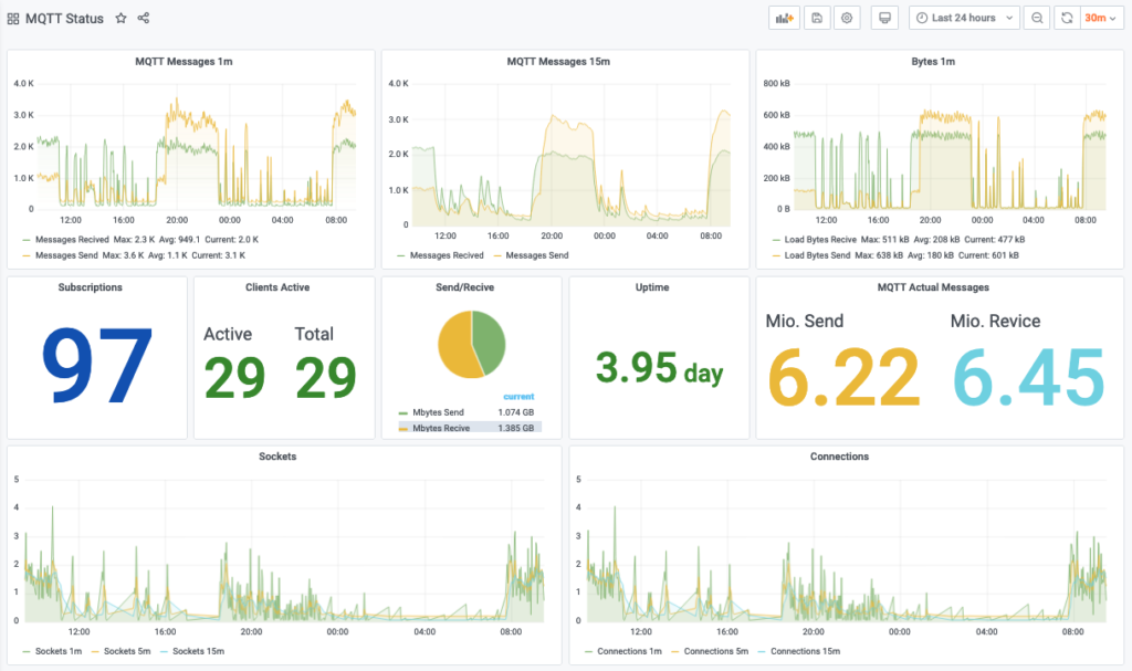
The Result in my Grafana Dashboard:

If you´ve questions or want to comment on one of my project please contact me on twitter: https://twitter.com/jarodw79

Energymeter with Gosund-SP111 and node-red2influx

node-red flow

Starting with the flow…

Prerequisits:

I assume that you´ve already installed node-red and connected it with your influxdb.
You should also have installed tasmota on your device. I´ve a Tuya device flashed with a actual Tasmota version by tuya-convert

I´ve used a Gosund SP111 for this, but you can basicaly use it with every device giving you SENSOR data. So it doesn´t matter whether you want to monitor temperature, gas, energy or other. You´ve just adapt where i used the $..ENERGY by chosing what ever your sensor provides. Other examples i use are „$..Illuminance“, „$..Pressure“, „$..Pressure“ and „$..Temperature“

Used elements:

  • MQTT in

With the MQTT in i subscribe to tele/+/SENSOR which is the default topic of tasmota for sensor values, here i make no selection what sensor values i will use so it gets every sensor type you have in your mqtt network

Here i use the JSONPath expression „$..ENERGY“ to filter only on JSON messages which includes ENERGY as a element.

  • Switch

I use the switch element to identifiy whether the supplyed element from JSONPath is empty or not.

  • Function

The function is where i add the source name within the JSON String to have that information afterwards available also in the influx measurements.

  • InfluxDB

After all i write the whole string in the influxDB in my statisitcs database in a measuremnt called „energy1“

  • DebugMsg

The DebugMsg element is to controll the output of the chain. In my environemnt this is a typical output:

[{„TotalStartTime“:“2020-05-21T19:09:01″,“Total“:1.591,“Yesterday“:0.208,“Today“:0.054,“Period“:0,“Power“:0,“ApparentPower“:17,“ReactivePower“:17,“Factor“:0.02,“Voltage“:228,“Current“:0.073″,“Name“:“energy2″}]

As you see there is the NAME added at the end of the object.

CODE:

[
{
„id“: „3a60f610.f66632“,
„type“: „jsonpath“,
„z“: „2c0c97dc.300d7“,
„expression“: „$..ENERGY“,
„split“: false,
„name“: „“,
„x“: 630,
„y“: 2080,
„wires“: [
[
„d5a418c2.d9bda8“
]
]
},
{
„id“: „d5a418c2.d9bda8“,
„type“: „switch“,
„z“: „2c0c97dc.300d7“,
„name“: „“,
„property“: „payload“,
„propertyType“: „msg“,
„rules“: [
{
„t“: „nempty“
},
{
„t“: „cont“,
„v“: „topic“,
„vt“: „msg“
},
{
„t“: „else“
}
],
„checkall“: „true“,
„repair“: false,
„outputs“: 3,
„x“: 790,
„y“: 2080,
„wires“: [
[
„e78d6b7c.6767c“
],
[],
[]
]
},
{
„id“: „e78d6b7c.6767c“,
„type“: „function“,
„z“: „2c0c97dc.300d7“,
„name“: „add name“,
„func“: „msg.payload[0].emname = msg.topic.split(\“/\“)[1];\nmsg.payload[0].Name = msg.topic.split(\“/\“)[1];\n\nreturn msg;“,
„outputs“: 1,
„noerr“: 0,
„x“: 940,
„y“: 2080,
„wires“: [
[
„76d65968.6c1568“,
„a78d055d.d1ea3“
]
]
},
{
„id“: „76d65968.6c1568“,
„type“: „influxdb out“,
„z“: „2c0c97dc.300d7“,
„influxdb“: „306f62ed.836df6“,
„name“: „Statistics“,
„measurement“: „energy1“,
„precision“: „“,
„retentionPolicy“: „“,
„x“: 1140,
„y“: 2080,
„wires“: []
},
{
„id“: „a78d055d.d1ea3“,
„type“: „debug“,
„z“: „2c0c97dc.300d7“,
„name“: „energy.raw“,
„active“: false,
„tosidebar“: true,
„console“: false,
„tostatus“: false,
„complete“: „true“,
„targetType“: „full“,
„x“: 1150,
„y“: 2040,
„wires“: []
},
{
„id“: „306f62ed.836df6“,
„type“: „influxdb“,
„z“: „“,
„hostname“: „influxdb“,
„port“: „8086“,
„protocol“: „http“,
„database“: „statistics“,
„name“: „“,
„usetls“: false,
„tls“: „“
}
]

WEMOS D1 Mini on Tasmota with AHT10 Sensor

Actual there are plenty of tutorials for thousands of sensors in IoT environment.
Due to the fact i´ve never found one for the AHT10 Sensor with Tasmota, i wrote one to share my experience with you.

Hardware preparation:

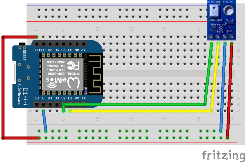
Connect AHT10 Sensor with the Wemos D1

Sensor – Wemos [color]
VIN – 3.3 V
GND – GND
SCL – D1 (GPIO5)
SDA – D2 (GPIO4)


I will directly jump to the specific task to activate the AHT10 Sensor in Tasmota.

I expect you have already installed and configured Arduino IDE oder platformIO

download Tasmota: https://github.com/arendst/Tasmota/archive/development.zip

Extract the ZIP file and open tasmota.ino in Arduino or platformIO  

Next is valid for acutal Tasmota 8.2.0.x
[Optional] Edit config:  my_user_config.h to have your wifi environment and mqtt setting directly set in the binary. If you don´t want to configure it here you can do it with a laptop or mobiel via the integrated wifi manager after booting the esp8266 the first time.

– set wifi settings
– set mqtt settings

Uncomment my_user_config.h line 496 to activate the AHT10 Sensor

The comment says only adress 0x38 but basicaly it supports 0x38 and 0x39 but for now only one sensor at a time.

Comment the following lines in the my_user_config.h out to prevent device drivers with the same ID 0x38 being active the same time.  

Dieses Bild hat ein leeres Alt-Attribut. Der Dateiname ist Bildschirmfoto-2020-05-01-um-22.45.08-1024x15.png
Line 455
Line 487

Now you can compile and transfer tasmota to your esp8266

Connect to Tasmota Page of device with http by typing the IP in your Browser:
– choose: Configuration
– than choose: Configure Module
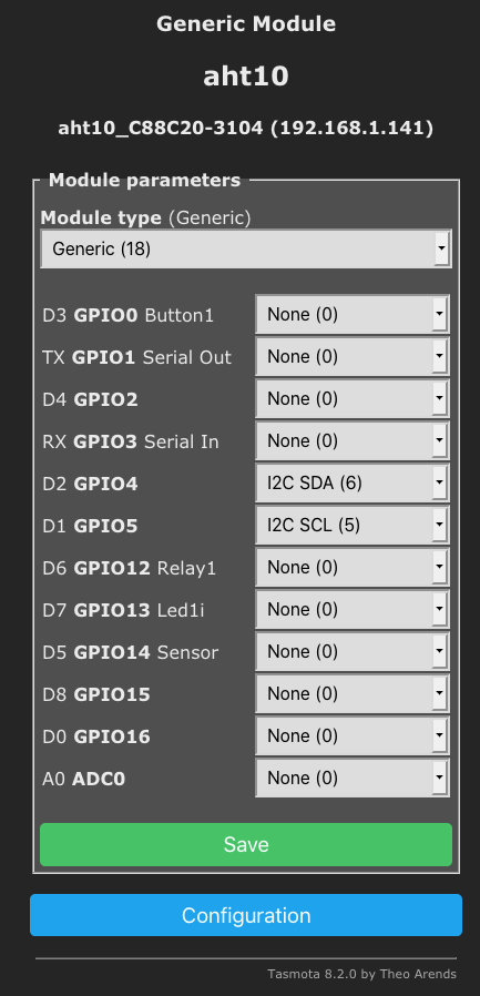
Module Type -> Generic
– Select SDA and SCL IO from the list
– D2 GPIO4 –> I2C SDA (6) 
– D1 GPIO5 –> I2C SCL (5)

Now if you reboot your Wemos you should see actual measurements.

If your settings are correct you should also get the measurements on mqtt if activated.
So you can use your newly installed AHT10 sensor in your smart home environment.

WEMOS D1 MINI

As described in my post before i will start with a short description of the WEMOS D1 MINI, one of my first ESP8266 boards.

Basically i user the mini as test board and in varius combinations as sensor base in my home automation setup.

Basic features:

  • integrated usb-serial connector
  • integrated voltage regulator
  • powered by usb 5V or direct via pin 5V & 3.3V
  • reset button (pin RST)
  • onboard led (pin D4)
  • integrated 4MB memory
  •  

Most of my wemos i use with DHT22 or BME260 sensors and tasmota: https://github.com/arendst/Sonoff-Tasmota/wiki/Wemos-D1-Mini

Some i also use with one or two DS18B20 temperature sensors.

In all use cases i connect via mqtt and use node-red to push the mqtt values to an influxDB.

The mini has the advantage that it´s compact/small but have more exposed GPIOs like the ESP-01 for example. It´s also possible to make small setups with a connected D0 -> RST for deep sleep scenarios with very low effort while you have to soldering very small structures on the ESP-01.

Powering the mini with a 18560 battery and a deep sleep cycle of about 3600sec allows operation for several weeks or month without a fixed power source.


Links:

One of the best pinout descriptions and detail sites i know for the esp8266:

ESP8266 Pinout Reference: Which GPIO pins should you use?


Save Google API via Node-Red in influxDB & visualize with grafana

I was inspired by a video from Csongor Varga for a new project idea with my Node-Red. Basically he uses Node-Red for requesting the Google API and getting the travel time form home to work. My idea was then to request the data from the Google API and save them in my InfluxDB for further analytics.

I start with a Big Timer to limit the requests to a timeslot from 4:30am to 10:30am. Then i use the Switch and Join elements to limit the request to any tenth trigger. After that there is the http get with the Google API call.

For the following three change elements which extracts the values i want to save i use a json element for transforming the output of the http call.

The last join than aggregates the values to a new json which is than forwarded to the influxdb in a database called statistics.

The output than looks like this in the influxDB

> select * from travel_allach ORDER BY time DESC limit 1;
name: travel_allach
time distance duration duration_in_traffic value
---- -------- -------- ------------------- -----
1570212851482806984 60696 3331 3143
>

This is the output of the Grafana Visualization:


Links:


ESP Overview

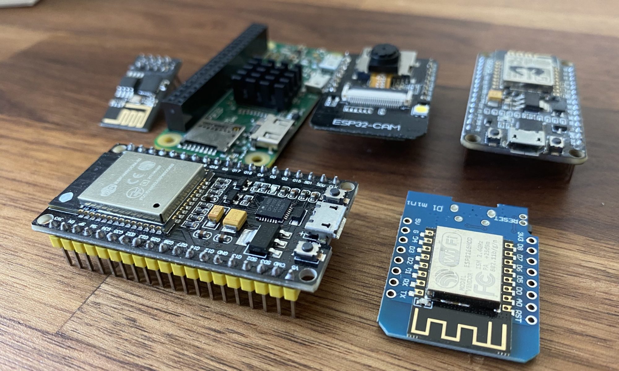
Actual it´s nearly impossible to count all the variations of the actual ESP8266 and ESP32 developer boards availaible at amazon, bangoods and ali express. Neverthe less i´ll try to document some of the boards i actual use and what they´re good for in some of the next posts.  Over the time i´ve collected many of the „standard“ representatives and also some of the more unusual types. They all have in common that they´re available for hobby developer and electronics nerds.

The power supply for most of them needs  3.3V or 5V depends on if there are voltage converters included or not. The main use cases most people see in this little boards are building cheap little IoT devices on their own.

The start of my short introduction round will be the:

WEMOS D1 MINI

which was the first ESP8266 i´ve started with.

Over the time I collected several other devices, like the Sonoff Basic, Sonoff Mini, NodeMCU ESP8266, ESP01, ESP32, OBI WIFI plugs, LILYGO TTGO T-Journal ESP32, Geekcreit® ESP32-CAM WiFi + bluetooth Camera Module, HiGrow ESP32 and some others i will also try to describe and how or for what i´m using this.

Home network

Actual i´ll have to do an inventory of my home network. Here is a short overview of how i´ve done it till now. Due to a relocation next year i´ve to rebuild most of the network and reorganize the network structure. There for i want to establish ne zones. Today there are 3 Zones in my network:

  1. Living
  2. Basement
  3. Garage

Every zone is connected via Powerline Modules. I´ve started with Powerline in 2010 with Belkin 1000 Gigabit Kit. After some years 2 off 4 modules where defect so i switched completly to TP-LINK TL-PA8030P KIT.

The network bandwith fluctuates but i get about 600Mbit to the basement form the first floor. and about 200MBit to the garage. Thats more than enough for a HD Video stream and controlling the garage door from a Raspberry Pi.

Core of my Network is a Fritz!Box 7590 + FRITZ!WLAN Repeater 1750E and a Synology DS-916+ with 8GB RAM an 16 GB Harddrives. For the basement i use a Fritz!Box 7360SL as WiFi AP and a BlackBox SmartSwitch for all connected devices. In the garage i use a Fritz!Box 7170 for Wifi and a Raspberry PI B 2.0 for the garage door opbener and a magnetic switch sensor to get the information about the door state. I will document the garage setting in a future post when i´ll set it up on the new location.